
Page 29 - metal2022
P. 29
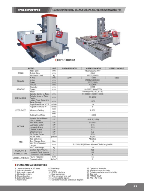
CNC HORIZONTAL BORING, MILLING & DRILLING MACHINE-COLUMN MOVEABLE TYPE


                                                 CBFK-130CNC/1


                         MODEL               UNIT     CBFK-130CNC/1       CBFK-130CNC/2       CBFK-130CNC/3
                          Table Size          mm                         1800x2000x0.001°
                TABLE     T-slots Size        mm                              28x9
                          Maximum Load        kg                           15000(20000)
                          X-Axis              mm          3200                 4200                5200
                          Y-Axis              mm                         (2000)2500(3000)
               TRAVEL
                          Z-Axis              mm                            2000(2500)
                          W-Axis              mm                             700(900)
                          Diameter            mm                              Φ130
               SPINDLE    Speed               rpm                       10~2000(2500)(3000)
                          Taper                                        7/24 taper ISO.50, BT-50
                          Spindle Center to Table  mm                  (0~2000)0~2500(0~3000)
                          Spindle Nose to Table
              DISTANCES   Center              mm                             50~2750
                          Height From Ground to   mm                          1520
                          Table Surface
                          Rapid Feed Rate X/Y/Z  m/min                         10
                          Rapid Feed Rate W  m/min                             6
                                             mm/
              FEED RATE   Minimum Setting                                     0.001
                                              min
                                             mm/
                          Cutting Feed Rate                                  1~5000
                                              min
                          Spindle Servo Motor-  kW                         15/18.5(22/26)
                          cont. / 30min
                          Axis X/Y/Z/W/B      kW                             9/7/9/4/7
                          Lubricator Motor    kW                              0.15
                MOTOR     Hydraulic Pump      kW                              2.25
                          Coolant Pump        kW                              1.17
                          Chip Conveyor       kW                               0.2
                          Oil Cooler Pump     kW                              0.75
                          No. of Tools       pieces                          40(60)
                          Tool Selection                                     Absolute
                 ATC      Tool Change Time    Sec.                             15
                          Max.Tool-Diameter/
                          Length              mm               Φ125/Φ250 (Without Adjacent Tool)/Length 400
                          Max. Tool Weight    kg                               25
              COOLANT &   Coolant Tank Volume  L                              400
             LUBRICATION  Hydraulic Tank Volume  L                             80
                                                                               8
                          Lubrication Tank Volume
                                              L
            MISCELLANEOUS  Power Required    KVA                               55
                          Pressurized Air    kg/cm 2                           6
               STANDARD ACCESSORIES
              I. Linear scales on X,Y,Z axes  8. Work lamp                 15. Operation manuals
              2. Spindle oil cooler       9. M.P.G.                        16. Machine inspection lists
              3. Automatic power off      10. RS232 interface              17. Splash guards (around the table)
              4. Hydraulic system         11. Heat exchanger               18. Tool box
              5. Coolant system           12. Chip conveyor and cart       19. FANUC OiMF
              6. Lubricator system        13. Leveling bolts & pads        20. ATC : 40 Tools
              7. Alarm lamp               14. Controller manuals and circuit diagram

                                                                                                                   27